

Product Brief
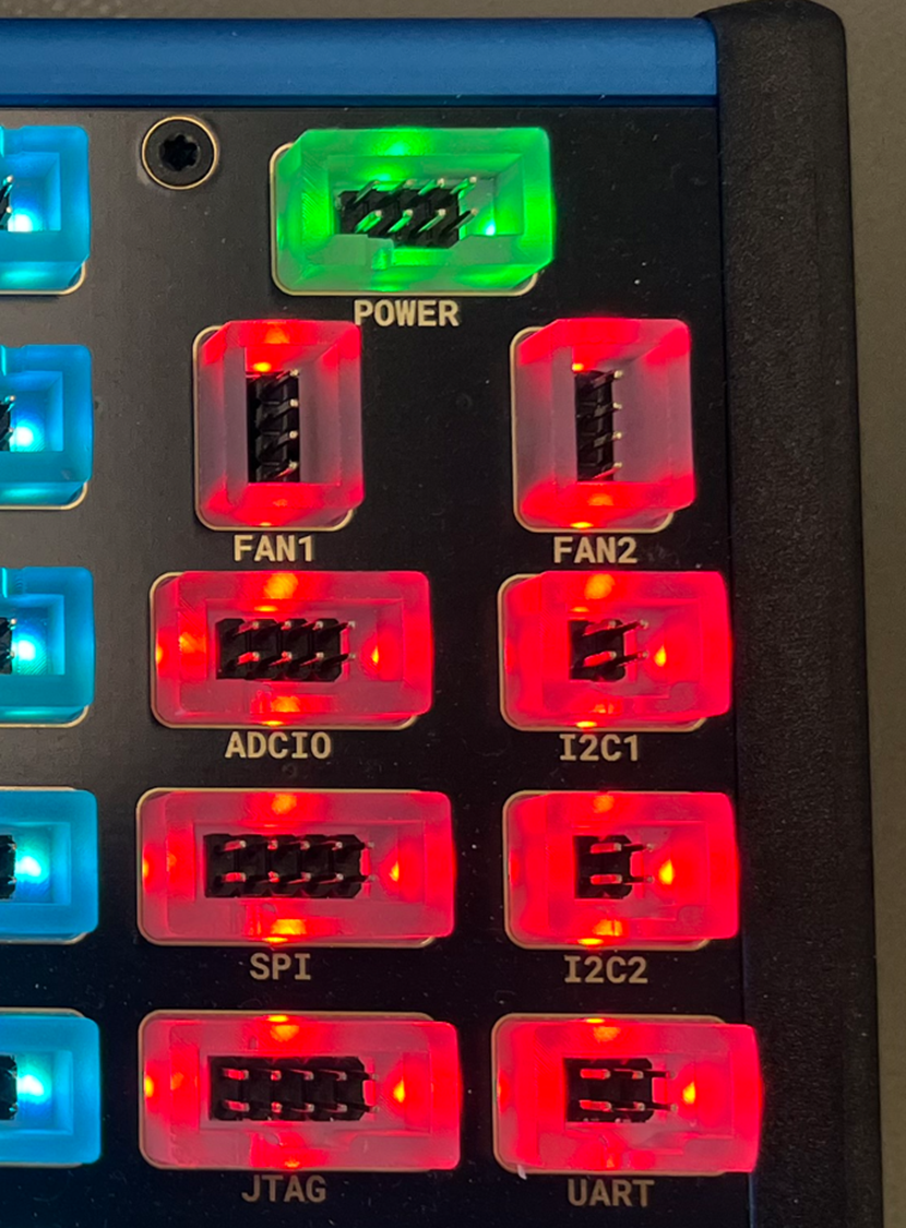
ESH10000359 is the communication and control module for your Accordion. It acts as the central coordination point between the host system and all peripheral modules.
The module provides configurable communication interfaces (I²C, UART, SPI, JTAG), voltage generation for attached buses, multi‑purpose analogue/digital I/O, fan control, status indication via RGB LEDs, and synchronized numeric data acquisition.
Typical use cases include:
-
PCBA bring‑up, boundary, and functional testing during NPI and production
-
Serving as a protocol hub controlling and powering DUT‑side interfaces
-
Environmental monitoring and thermal management inside test fixtures
-
High‑speed analogue sampling for leakage, rail monitoring, and sensor evaluation
The module is designed to be fully software‑defined and operated through Accordion APIs from C#, Python, or test frameworks.
Datasheet
|
Parameter |
Specification |
|
Module type |
N5 TOP communication and control |
|
Communication interfaces |
2× I²C, UART (RS232), SPI, JTAG |
|
I²C enable & pull‑ups |
Per‑channel, software‑controlled |
|
UART default |
/dev/serial0, 9600 baud |
|
Analogue / DAC resolution |
12‑bit |
|
Analogue voltage range |
0–5 V (double ADC/DAC range enabled) |
|
Analogue channels |
4× VOUT, 4× MPIO |
|
Pseudo‑digital support |
Yes (MPIO, VL/VH thresholds) |
|
Special I/O modes |
Open‑drain, float (MPIO) |
|
Fan control |
2× PWM, tachometer feedback |
|
Fan controllers |
2× MAX6650 |
Manual
System overview
ESH10000359 is typically installed as the top module (ModuleIndex = 15). All user‑accessible channels follow the naming scheme:
{ModuleIndex}.ESH10000359.{ChannelName}
Example:
15.ESH10000359.I2C1
Communication interfaces
I²C
-
Two independent I²C channels
-
Each channel has:
-
Enable control (I2C1_EN, I2C2_EN)
-
Software‑controlled pull‑ups (I2C1_PU, I2C2_PU)
-
Dedicated voltage output (I2C1_VOUT, I2C2_VOUT)
-
Recommended sequence:
-
Set VOUT to required bus voltage
-
Enable pull‑ups if needed
-
Enable I²C channel
-
Execute transactions
UART
-
RS232 signalling
-
Automatically enabled on access
-
Baudrate configurable in software
-
Dedicated voltage output (UART_VOUT)
SPI and JTAG
-
Shared voltage output (SPI_JTAG_VOUT)
-
Explicit enable required (SPI_EN, JTAG_EN)
Analogue and digital I/O
VOUT channels
-
Output‑only
-
Used to supply communication buses or DUT rails
-
0–5 V range
Channels:
-
I2C1_VOUT
-
I2C2_VOUT
-
UART_VOUT
-
SPI_JTAG_VOUT
MPIO channels
-
Bidirectional
-
Operate in:
-
Analogue mode (ADC/DAC)
-
Pseudo‑digital mode (threshold‑based)
-
Pseudo‑digital behaviour is defined using VL and VH thresholds. Special modes:
-
Open‑drain: VH < 0
-
Floating output: VL < 0
Use cases:
-
GPIO emulation
-
Voltage sensing
-
Presence and leakage detection
Fan control
-
Two independent fans
-
Ratiometric speed control (0.0–1.0)
-
Configurable maximum RPM per fan
-
Tachometer feedback available for runtime verification
Channels per fan:
-
FANx
-
FANx_MAX_RPM
-
FANx_FREQ
Use FAN_INHIBITn to disable fans at hardware level.
LED status indication
-
Eight RGB LEDs mapped to system functions
-
Colour controlled by named colours or hex values
-
Global luminance control
LEDs:
-
I2C1, I2C2, UART, SPI, JTAG
-
POWER
-
FAN
-
ADCIO
Intended for operator feedback and fast diagnostics during production.
Numeric result acquisition
-
High‑speed, synchronized sampling from analogue channels
-
Supports multi‑channel acquisition
-
Optional reduced result set for large data volumes
Typical usage:
-
Leakage testing
-
Rail stability checks
-
Sensor characterization
Results are transferred as base64‑encoded numeric sets.
Error handling
The module validates:
-
Channel existence
-
Voltage threshold limits
-
Threshold ordering (VH > VL)
-
Colour formatting
Communication and bus errors are returned to the caller and should be handled at test‑step level.
Pinout
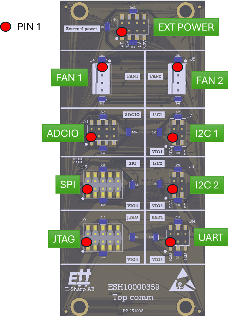
EXT POWER
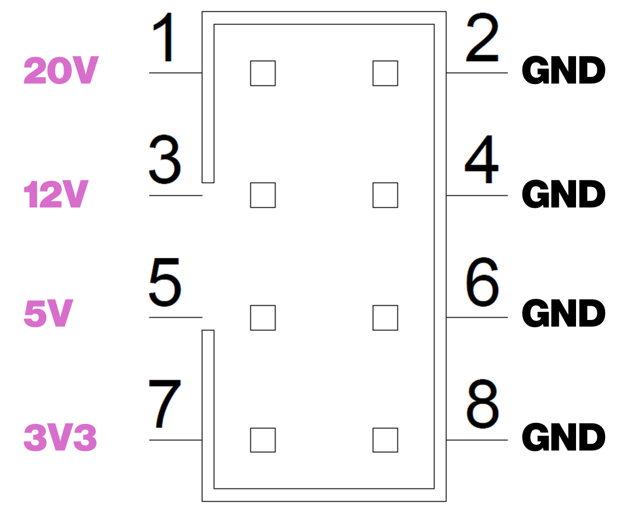
Pin
|
Name
|
Type
|
Description
|
|---|---|---|---|
1
|
20V
|
Power
|
20V always on, 0.5A thermal fuse
|
3
|
12V
|
Power
|
12V always on, 0.5A thermal fuse
|
5
|
5V
|
Power
|
5V always on, 0.5A thermal fuse
|
7
|
3V3
|
Power
|
3V3 always on, 0.5A thermal fuse
|
2, 4, 6, 8
|
GND
|
Power
|
Ground reference
|
I2C [1-2]
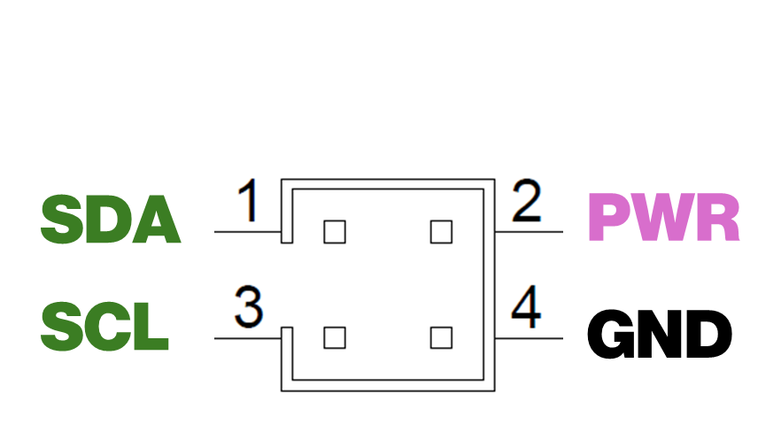
Pin
|
Name
|
Type
|
Description
|
|---|---|---|---|
1
|
SDA
|
Bidirectional
|
SDA signal of I2C bus. Can switch in/out pull-up resistor 1k to VI2C
|
2
|
VI2C
|
Power
|
Programmable I2C power output 0-5V
|
3
|
SCL
|
Output
|
SCL signal of I2C bus. Can switch in/out pull-up resistor 1k to VI2C
|
4
|
GND
|
Power
|
Ground reference
|
FAN [1-2]
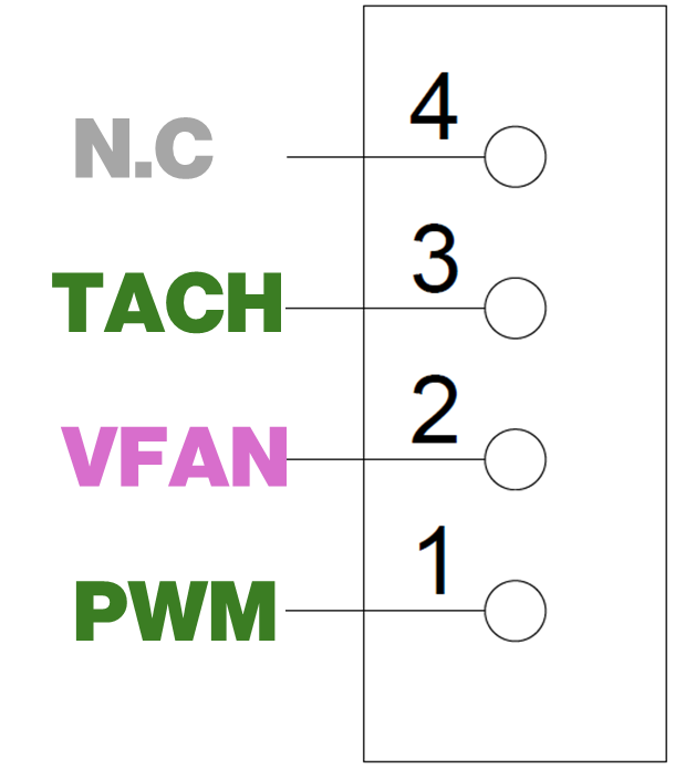
Pin
|
Name
|
Type
|
Description
|
|---|---|---|---|
1
|
PWM
|
Output
|
PWM output to fan
|
2
|
VFAN
|
Power
|
Switchable fan power, selectable 5V/12V
|
3
|
TACH
|
Input
|
Tachometer input
|
4
|
N.C
|
-
|
No connect
|
ADCIO
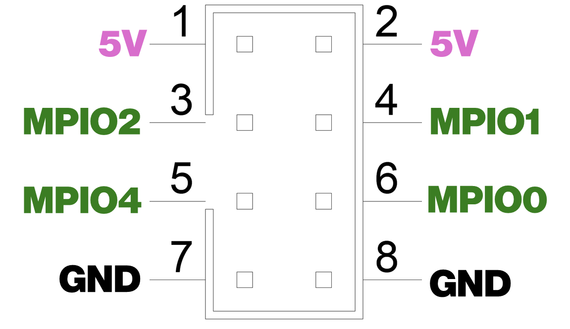
Pin
|
Name
|
Type
|
Description
|
|---|---|---|---|
1,2
|
5V
|
Power
|
5V always on, 0.5A thermal fuse
|
3
|
MPIO2
|
Bidirectional
|
Programmable analog/pseudo-digital 0-5V
|
4
|
MPIO1
|
Bidirectional
|
Programmable analog/pseudo-digital 0-5V
|
5
|
MPIO4
|
Bidirectional
|
Programmable analog/pseudo-digital 0-5V
|
6
|
MPIO0
|
Bidirectional
|
Programmable analog/pseudo-digital 0-5V
|
7,8
|
GND
|
Power
|
Ground reference
|
SPI
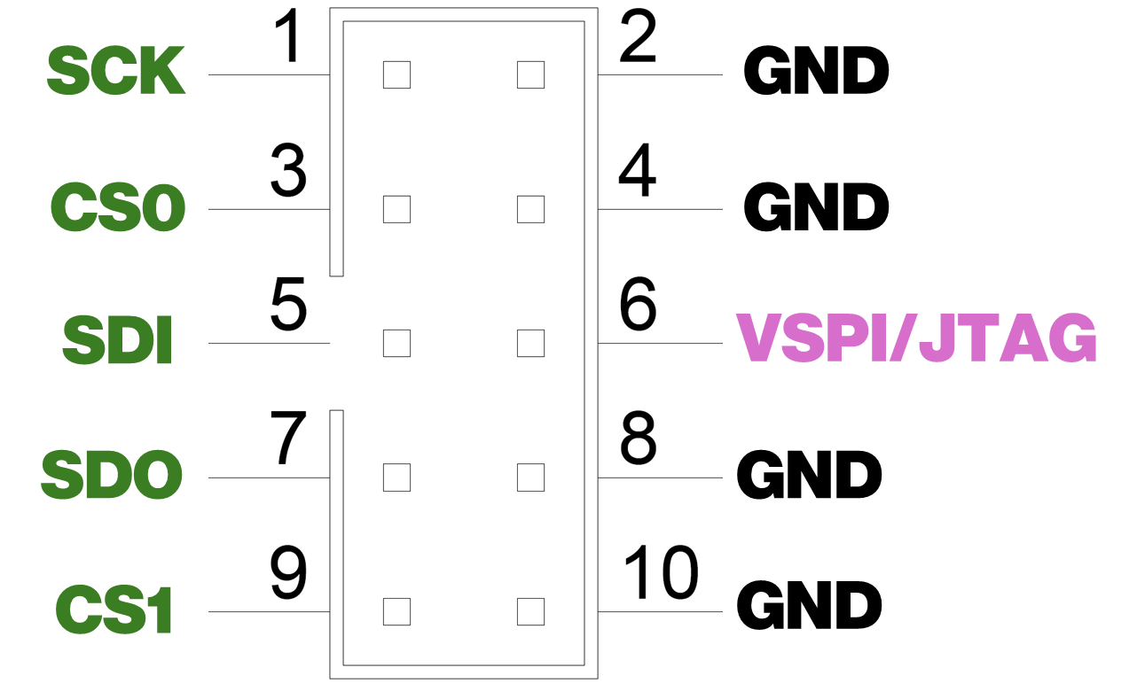
Pin
|
Name
|
Type
|
Description
|
|---|---|---|---|
1
|
SCK
|
Output
|
SPI Clock
|
2,4,8,10
|
GND
|
Power
|
Ground reference
|
3
|
CS0
|
Output
|
SPI Chip Select 0
|
5
|
SDI
|
Input
|
SPI Serial Data In
|
6
|
VSPI/JTAG
|
Power
|
Programmable output power 0-5V. Note, shared between JTAG and UART
|
7
|
SDO
|
Output
|
SPI Serial Data Out
|
9
|
CS1
|
Output
|
SPI Chip Select 1
|
JTAG
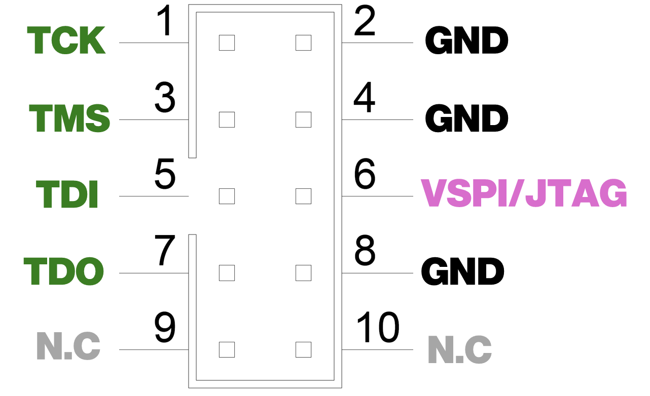
Pin
|
Name
|
Type
|
Description
|
|---|---|---|---|
1
|
TCK
|
Output
|
JTAG Test Clock
|
2,4,8
|
GND
|
Power
|
Ground reference
|
3
|
TMS
|
Output
|
JTAG Test Mode Select
|
5
|
TDI
|
Input
|
JTAG Test Data In
|
6
|
VSPI/JTAG
|
Power
|
Programmable output power 0-5V. Note, shared between JTAG and UART
|
7
|
TDO
|
Output
|
JTAG Test Data Out
|
9,10
|
N.C
|
-
|
No connect
|
UART
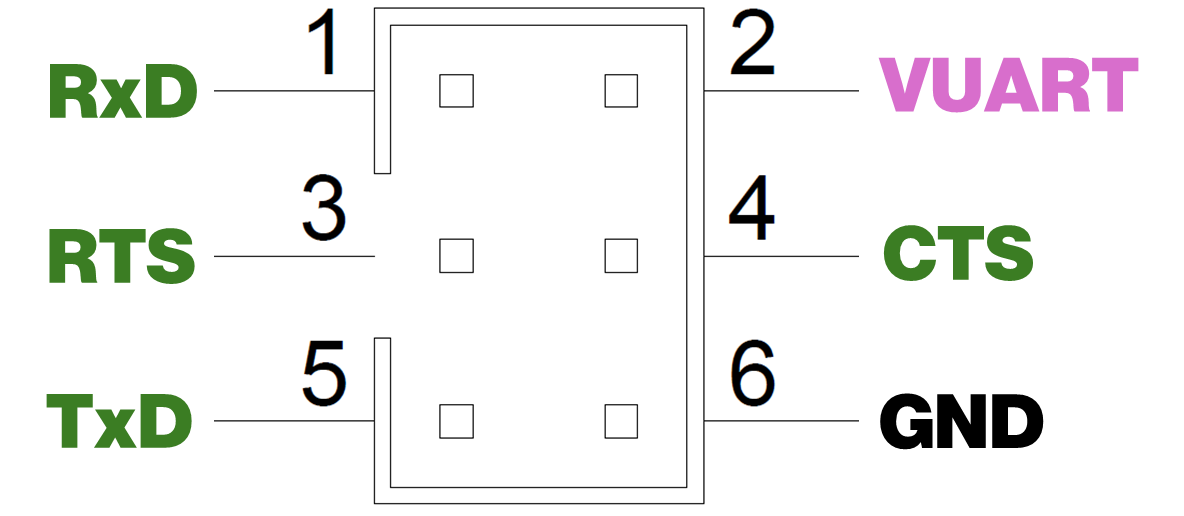
Pin
|
Name
|
Type
|
Description
|
|---|---|---|---|
1
|
RxD
|
Input
|
Receive Data
|
2
|
VUART
|
Power
|
Programmable output power 0-5V
|
3
|
RTS
|
Input
|
Ready to Send
|
4
|
CTS
|
Output
|
Clear to Send
|
5
|
TxD
|
Output
|
Transmit Data
|
6
|
GND
|
Power
|
Ground reference
|