

Product Brief
The ESH10000582 is a compact 100 W programmable boost power supply powered entirely by a standard USB-C PD charger. It accepts a negotiated USB PD input voltage (5 V – 20 V) and delivers a selectable DC output in the range of 9 V to 56 V, making it suitable for consolidating a wide variety of fixed-voltage power adapters into a single USB-C source.
The unit is housed in a Hammond 1455C801 extruded aluminium enclosure (80 × 54 × 23 mm). All output voltage and input voltage settings are configured via internal DIP switches. Front-panel LEDs provide at-a-glance status for input, output, and thermal condition; an external CTRL signal allows hardware-controlled output enable/disable.
Typical use cases include:
-
Replacing multiple fixed-voltage power adapters with a single USB-C PD source in field, lab, or production environments
-
Powering embedded systems, sensors, motors, or industrial devices that require voltages not natively available from USB-C (e.g. 24 V, 48 V)
-
Bench supply for prototyping and verification where only USB-C power is available
-
Portable power for equipment requiring 9 V – 56 V from a laptop charger or power bank
-
Hardware-controlled power sequencing via the CTRL interface in automated test rigs
Datasheet
|
Parameter |
Value |
Notes |
|---|---|---|
|
Input interface |
USB-C (USB PD) |
PD negotiation required |
|
Input voltage options |
5 V, 9 V, 12 V, 15 V, 20 V |
Requested via USB PD; DIP switch selectable |
|
Output voltage options |
9 V, 12 V, 15 V, 24 V, 48 V, 56 V |
DIP switch selectable |
|
Max output power |
100 W |
Requires a 100 W capable USB PD charger; limited to input power |
|
Topology |
Boost |
Vout must always be greater than Vin |
|
Efficiency (typical) |
~95% |
|
|
Output voltage accuracy |
±1% of setpoint |
Set by 0.1% resistors and LM5022 reference tolerance |
|
Power good threshold |
±5% of setpoint |
Out LED turns red when outside this window (no hysteresis) |
|
Max transient overshoot / undershoot |
~2% |
|
|
Enclosure |
Hammond 1455C801 |
80 × 54 × 23 mm (L × W × H) |
|
Compliance |
CE, RoHS, REACH |
|
Thermal protection
|
Event |
Threshold |
Behaviour |
|---|---|---|
|
Overtemperature trip |
85 °C |
Output disabled; OT LED turns red |
|
Overtemperature recovery |
75 °C |
Output resumes or returns to standby (see Disable Standby setting) |
Overtemperature is unlikely under normal operating conditions with adequate ambient ventilation. The unit does not require forced airflow in typical installations.
Maximum output current by Vin and Vout
Values assume ~95% efficiency and standard USB PD maximum power per voltage tier. Actual available power depends on the charger; refer to your charger's specifications.
|
Vout |
5 V in *
|
9 V in
|
12 V in ***
|
15 V in
|
20 V in
|
|---|---|---|---|---|---|
|
9 V |
1.6 A |
— Vout ≤ Vin (invalid) |
|||
|
12 V |
1.2 A |
2.1 A |
— Vout ≤ Vin (invalid) |
||
|
15 V |
1.0 A |
1.7 A |
2.3 A *** |
2.9 A |
— Vout ≤ Vin (invalid) |
|
24 V |
— insufficient ** |
1.1 A |
1.4 A |
1.8 A |
4.0 A |
|
48 V |
— insufficient ** |
0.5 A |
0.7 A |
0.9 A |
2.0 A |
|
56 V |
— insufficient ** |
0.5 A |
0.6 A |
0.8 A |
1.7 A |
'* Depending on the USB PD charger, 5 V may not be a reliable power source. Not all chargers guarantee full USB PD compliance at 5 V under load.
** 5 V input does not provide sufficient power for Vout > 15 V.
*** 12 V input may not be supported by all USB PD chargers.
DIP switch — Vin (internal)
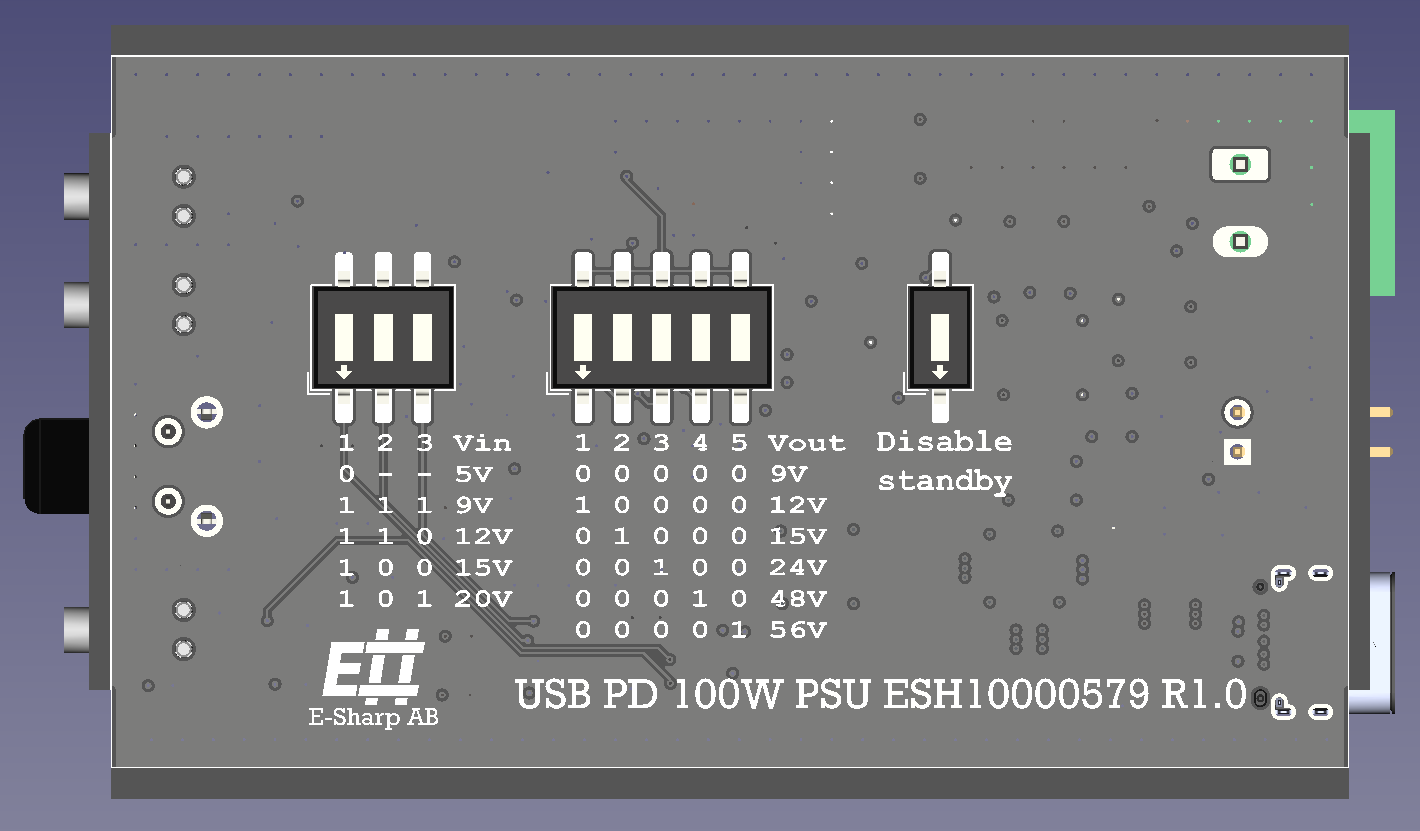
Selects the USB PD voltage tier requested from the charger. Located inside the enclosure.
|
SW1 |
SW2 |
SW3 |
Requested Vin |
|---|---|---|---|
|
0 |
– |
– |
5 V |
|
1 |
1 |
1 |
9 V |
|
1 |
1 |
0 |
12 V |
|
1 |
0 |
0 |
15 V |
|
1 |
0 |
1 |
20 V |
*** 12 V may not be supported by all USB PD chargers.
DIP switch — Vout (internal)
Selects the output voltage. Only one switch should be ON at a time. All switches OFF selects 9 V.
|
SW1 |
SW2 |
SW3 |
SW4 |
SW5 |
Vout |
|---|---|---|---|---|---|
|
0 |
0 |
0 |
0 |
0 |
9 V |
|
1 |
0 |
0 |
0 |
0 |
12 V |
|
0 |
1 |
0 |
0 |
0 |
15 V |
|
0 |
0 |
1 |
0 |
0 |
24 V |
|
0 |
0 |
0 |
1 |
0 |
48 V |
|
0 |
0 |
0 |
0 |
1 |
56 V |
This is a boost converter. Vout must always be set greater than Vin. Setting Vout ≤ Vin is not supported.
DIP switch — Disable standby (internal)
Single switch. Controls power-on behavior:
-
OFF (0): Device starts in standby when power is applied. Press the front-panel Power button to enable output.
-
ON (1): Output is enabled automatically as soon as USB power is applied. No button press required.
Manual
Initial setup
-
Open the enclosure and configure the three DIP switch banks: Vin, Vout, and Disable Standby.
-
Connect the load to the Power out terminal (front face).
-
Connect a USB-C PD charger rated for the desired input tier. For full 100 W output, a 100 W PD charger is required.
-
If Disable Standby is OFF, press the Power button to enable output.
Front panel
The front panel has three status LEDs and one push-button.
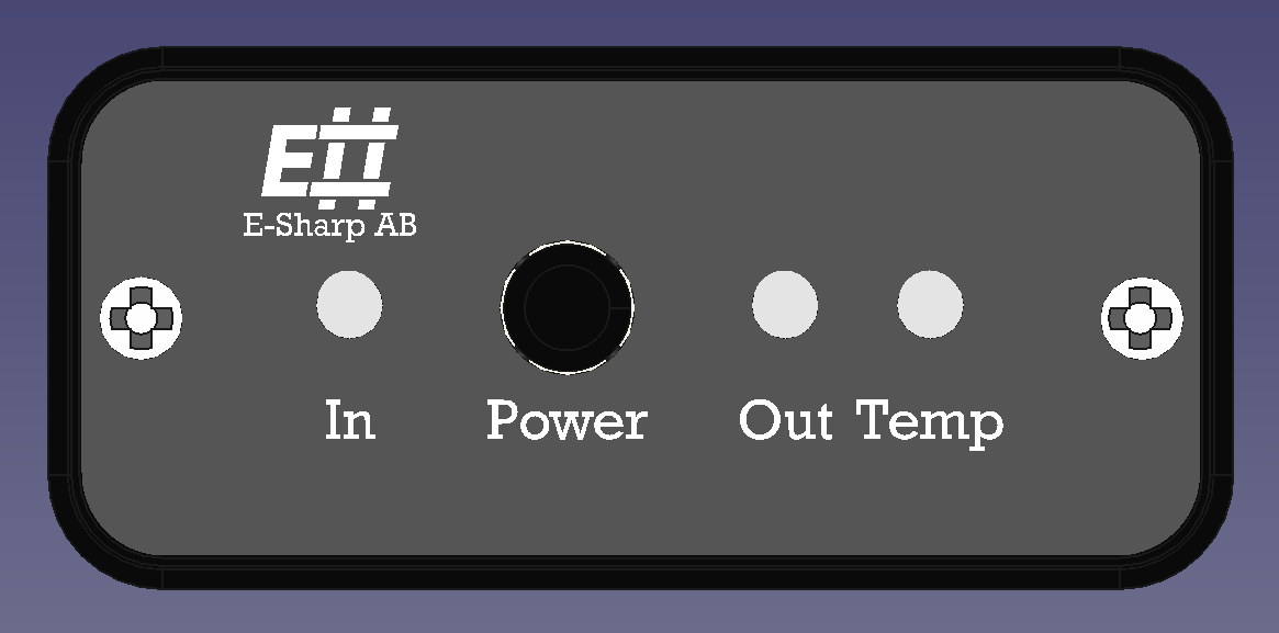
In LED
Green – USB PD negotiation succeeded; charger is supplying the requested voltage.
Red – USB PD negotiation failed; the charger cannot supply the requested voltage tier.
Out LED
Blue – Output is in standby (disabled).
Green – Output is active and within ±5% of the set voltage.
Red – Output is active but out of tolerance (>±5% from setpoint).
OT (overtemperature) LED
Off – Temperature is normal.
Red – Internal temperature has exceeded 85 °C; output is disabled.
Power button
Toggles between standby and output-enabled states. When the device is in standby, pressing the button enables the output. When the output is active, pressing the button returns the device to standby.
Overtemperature behavior
When the internal temperature exceeds 85 °C, the output is disabled and the OT LED turns red. The output remains off until the temperature drops below 75 °C. Recovery behaviour then depends on the Disable Standby DIP switch:
-
Disable Standby ON: Output resumes automatically when OT clears.
-
Disable Standby OFF: Device returns to standby when OT clears. Press the Power button to re-enable.
CTRL interface
The rear-panel CTRL connector allows hardware-controlled output disable. Shorting the two pins together disables the output. Removing the short re-enables it (subject to Disable Standby and standby state).
The device will not enter standby mode while CTRL is actively asserted (shorted). It is advisable to set Disable Standby ON when using CTRL, so the device returns to output-enabled state when the CTRL signal is released.
Power budget considerations
Output power is limited to the power delivered by the USB PD source. At ~95% efficiency, a 20 V / 5 A (100 W) charger can deliver approximately 95 W at the output terminals. To sustain the full rated output, the charger must negotiate 20 V at 5 A.
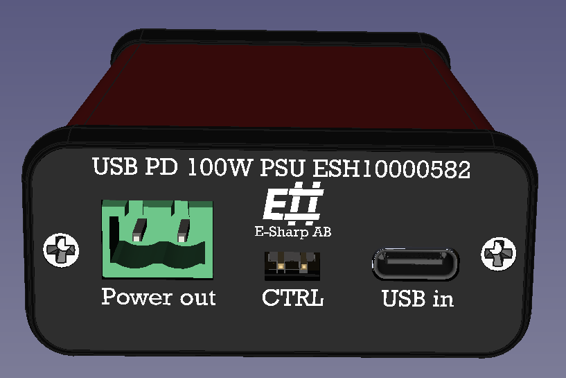
Connectors
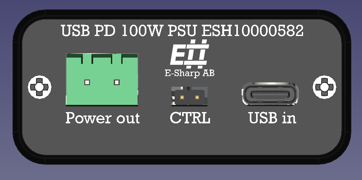
Power out — rear panel
2-pin push-pull pluggable terminal block, 5.0 mm pitch (DB2ERC-5.0-2P-GN).
Pin 1 (left)V outPositive output
Pin 2 (right)GNDReturn / ground
CTRL — rear panel
2-pin male header, 2.54 mm pitch.
Pin 1 (left)CTRLControl input
Pin 2 (right)GNDReference ground
Output is disabled when Pin 1 is pulled to GND (Pin 2). Pin 1 is pulled up internally to 3.3 V via a 10 kΩ resistor. A 70 V series diode allows open-drain drivers operating at voltages above 3.3 V to be used directly; the control GND is common with power GND.
The device will not enter standby mode while CTRL is actively asserted. It is advisable to set Disable Standby ON when using CTRL, so the device returns to output-enabled state when the CTRL signal is released.
USB in — rear panel
USB Type-C receptacle. USB PD negotiation is performed automatically at power-on based on the Vin DIP switch setting. Use a USB PD compliant charger.